I suppose this post is a little out of order. It should have preceded Rimage DTP-4500 RAS 13 Initialization Sequence
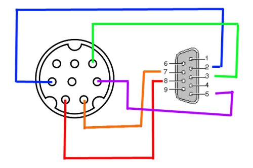
I had popped the side off my RAS 13 and looked at the port that had been used to control the autoloader. It was a mini din 8 pin port. It was connected to a serial level converter chip. I took this as a sign it used RS232. There were 4 pins actually connected to the chip, 1, 2, 3, and 8. Pin 5 was connected to ground. Picture: Control PCB inside RAS 13
Some trial and error with the breadboard. Picture: Messy Breadboard
Once I had the proof of concept, I wanted to order some connectors to make it a little tidier.
Diagram of cable connection. Note: both ends are looking into male connectors. Check out my Skills of an Artist!
Connectors are pretty easy to find. I ordered from mouser and sparkfun since I was ordering other stuff too.
